HVI Conductors
High-voltage-resistant, insulated down conductor for maintaining the separation distance to electrically conductive parts. Can be used for an equivalent separation distance of up to s ≤ 75 cm (in air) or s ≤ 150 cm (solid building material).
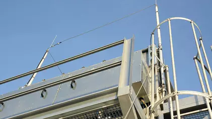
Supporting Tube with HVI Conductor
Optically optimised installation of the HVI Conductor inside the supporting tube creates less wind exposed surface.
For use up to an equivalent separation distance s ≤ 75 cm (in air) or s ≤ 150 cm (solid material).
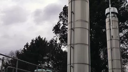
Conductor length to be indicated when ordering (steps of 0.5 m).Product detailsAir-Termination Mast with HVI Conductor
For a maximum free length of the whole air-termination system of 8.5 m.
To be fixed with three variable supports (Part No. 105 345).
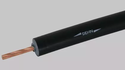
Transport length 6000 mm.Product detailsHVI Conductor / HVI long Conductor
High-voltage-resistant, insulated down conductor for keeping the separation distance to electrically conductive parts according to IEC 62305-3.
For use up to an equivalent separation distance s ≤ 75 cm (in air) or s ≤ 150 cm (solid material).Product detailsConnection Elements for HVI long Conductor
Product detailsSupporting Tubes for HVI long Conductor
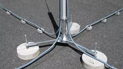
Product detailsTripod for Supporting Tubes without Side Outlet
Stands for holding HVI supporting tubes for internally/externally routed HVI Conductors in/on the supporting tube, with double clamp for connection of 2x Rd 8–10 mm. Adjustable to the roof slope up to max. 10° using a variable fixing on the base holder.
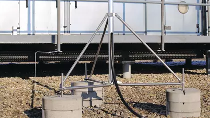
The stackable concrete bases, the plastic base plates and the base holder set for holding additional concrete bases are each available separately in the accessories.Product detailsTripods for Supporting Tubes with Side Outlet
Stands for holding HVI supporting tubes for internally/externally routed HVI Conductors in/on the supporting tube, with double clamp for connection of 2x Rd 8–10 mm. Adjustable to the roof slope up to max. 10° using a variable fixing on the base holder.
The stackable concrete bases, the plastic base plates and the base holder set for holding additional concrete bases are each available separately in the accessories.Product detailsFixing Elements for Supporting Tubes
Product detailsSpacers for Omnidirectional Antennas
Product detailsAccessories for HVI Conductor and HVI long Conductor
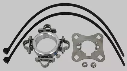
Product detailsConductor Holders for HVI Conductor in Ex Areas
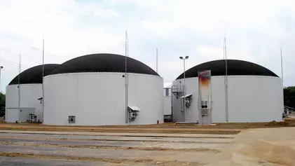
The HVI Conductor is suitable for use in explosion hazardous areas of Ex zone 1 (gases, vapours, mists) as well as Ex zone 21 (dusts). The special installation conditions safely prevent electric sparks to neighbouring metal parts when lightning current flows through the HVI Conductor.
The HVI Conductor has to be installed in explosion hazardous areas in accordance with the installation instructions.Product detailsStripping tool for HVI, HVI light, HVI light plus Conductors
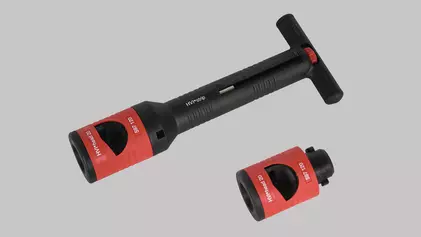
Tool for stripping the semi-conductive sheath and the PE insulation of the HVI light Conductor, HVI Conductor (outer diameter 20 mm).- The tool consists of a handle and various interchangeable stripping inserts
- The stripping length of the HVI light Conductor, HVI light plus Conductor, HVI Conductor is adjustable in steps of 0.2 mm (lock points) using the knob in the handle. The dial on the handle shows the length that is set.
Operation
Position the stripping insert at the cut-off end of the conductor.
Turn clockwise applying light pressure, the cutting operation/stripping occurs through the tool.
The interchangeable stripping insert can be attached without tools via the bayonet coupling.Product details